Features:
Assembly Guide
Relay Datasheet
NOTE: This PCB is built for a breadboard or low signal protoboard. A typical solderless breadboard's contacts are rated for 5V at 1A, or 15 Volts and 333mA. Just because the relay is rated for bigger stuff, doesn't mean you should run big stuff through your breadboard. Don't do it!
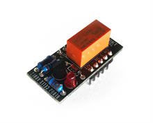
- Tiny and breadboard/protoboard-friendly, leaving plenty of room for other connections
- 5V or 12V DPDT non-latching relay, with LED showing active state
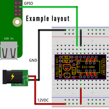
- Built-in transistor control makes it easy to trigger via the 3.3V or 5V logic levels of GPO from Raspberry Pi/Arduino/etc
- Assembled versions are made and fully tested by a human - ships in anti-static bag
- Kits are great for a little soldering project or for educational purposes
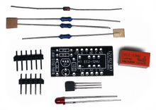
- Kits arrive in an anti-static bag containing all electronic components, bare PCB, headers, and link to downloadable assembly guide online
Product Description:
This series of small breadboard-ready relay breakout boards was brought about while prototyping audio circuits. The relays with non-breadboard-friendly pitches that were being tested with became frustrating, so it was decided to fab some modular options that can be placed neatly on a breadboard or a more permanent protoboard.
This version uses a 5V or 12V non-latching DPDT relay. Also included is transistor control to make it easy to trigger via the 3.3V or 5V logic levels of GPO from Raspberry Pi/Arduino/etc, and an LED to indicate an active state. Basically, this relay breakout board gets you two independent switches, driven by a single control signal.
InstructionsAssembly Guide
Relay Datasheet
Relay Specs:
EC2-5NU / EC2-12NU Contact Ratings:- Maximum Switching Power 60 W, 125 VA
- Maximum Switching Voltage 220 VDC, 250 VAC
- Maximum Switching Current 2 A
- Maximum Carrying Current 2 A
Dimensions:
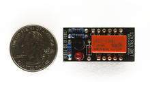
- 33.4mm x 15.9mm (1.31in x .63in)
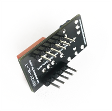
- Header pins are standard 2.54mm (.100") pitch
NOTE: This PCB is built for a breadboard or low signal protoboard. A typical solderless breadboard's contacts are rated for 5V at 1A, or 15 Volts and 333mA. Just because the relay is rated for bigger stuff, doesn't mean you should run big stuff through your breadboard. Don't do it!


